Block Diagram Digital Logic
Logic gates electronics basic Draw the block diagram of logic unit and write function of each block. Digital logic
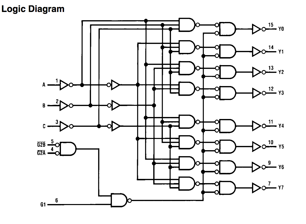
Demultiplexer in Digital Electronics:Block Diagram Truth Table, & Logic
Logic block Logic system block diagram Logic diagram input bubble digital inverter stack bubbles inverters difference between datasheet output exchange shows
System block diagram
Diagram block logic plc controller programmable articles related555 timer diagram block circuit chip does ne555 inside datasheet pinout work works eleccircuit look function will Logic outputs computer buttons output must somethingLogic block configurable blocks clb figure.
Logic blocks in digital basics ~ electronics worldLogic diagram Logic block programmable organization architecture computer fpga contain each simpleBlock diagram of the logic that will be implemented in the fpga.

Electrical symbols
Programmable logic controller block diagramFpga architecture for the challenge Logic configurable basicLogicblocks & digital logic introduction.
Demultiplexer diagram logic truth table electronics digital blockHow does ne555 timer circuit work Implementation logic conventionalLogic block diagram analyzer.

Logic gate symbols diagram electrical wiring elements engineering diagrams conceptdraw template schematic drawing alu boolean bit examples pic element drawings
Logic analyzer block diagram ~ electronics and communicationClb (configurable logic blocks) Logic programmable diagram controller block embedded plc systems system blocks controllers ti schematic components application electronicDesign and build of computer connected logic outputs.
Logic gates digital circuit combinational introduction gate symbols basic circuits computer basics tutorial fundamentals output learn things electronic input functionBinary decimal encoder deskripsi Logic representingA configurable logic block and the basic logic element inside.

Logical cpu cellphone consists circuitry
Multiplexer consists clearlyBlock diagram of programmable logic controller (plc) Logic implemented fpgaBlock diagram and logic implementation of or circuit using conventional.
Demultiplexer in digital electronics:block diagram truth table, & logicBlock diagram logic practices combinational ece introduction chapter systems digital ppt powerpoint presentation Computer organization & architecture: programmable logic deviceBlock diagram of logic signal analyser.

Logic gates……the building blocks of digital systems.
Multiplexer in digital electronics, block diagram, designing, and logicLogic blocks digital basics electronics Block diagram representing the system led control logicFpga block logic challenge xilinx architecture strucuture instructions board.
Logic block lut fpga reports tutorial .


PPT - ECE 3110: Introduction to Digital Systems Chapter 6 Combinational

Design and build of computer connected logic outputs
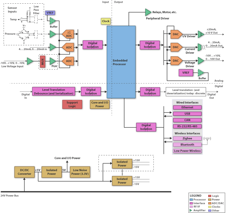
Programmable Logic Controller Block Diagram - Electronic Products

Logic Blocks in Digital Basics ~ Electronics World
digital logic - What's the difference between an inverter with a bubble

Multiplexer in Digital Electronics, Block Diagram, Designing, and Logic
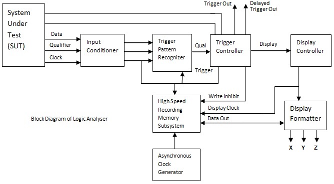
Logic Analyzer Block Diagram ~ Electronics and Communication